FAQ
How to mount a sensor spot?
The oxygen sensor spot should be integrated into a dry, clean vessel (humidity or oily residues affect the adhesion and may lead to a detaching of the sensor spot from the vessel wall). The adhesion surface area of the vessel wall should be plane or slightly arched but not strongly curved or corrugated. Otherwise, the spot may detach partly from the vessel wall during the curing process of the silicon glue due to the tension of the spot.
The silicon glue should be cured for at least 60 min. before the test vessel is fill.
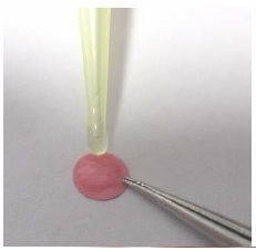
Apply a small amount of silicon glue (D5-Spot: ca. 4 µL) onto the red side of the spot.
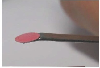
Position the spot on the plane bent end of a spatula.
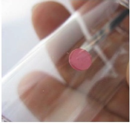

Attach the spot to the inside wall of the test vessel.
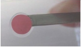
Shift the sensor spot slightly with little pressure onto the surface so that a small ring of silicon glue emerges around its edge.
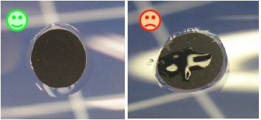
No air should be enclosed in the silicon layer between spot and vessel wall.
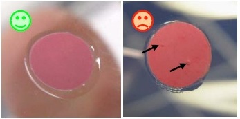
Silicon stains on the black sensor surface should be avoided since they increase the response time of the sensor.
LinkWhat is a Shuttle Box?
The Loligo® shuttle tanks are modified versions of the classic operant conditioning chambers (also known as the Skinner box) used for experimental analysis of behavior, e.g. to study operant conditioning and classical conditioning in animals.
An operant conditioning chamber permits experimenters to study behavior conditioning (training) by teaching a subject animal to perform certain actions (like pressing a lever) in response to specific stimuli like a light or sound signal. When the subject correctly performs the behavior, a mechanism delivers food or another reward. In some cases, the mechanism delivers a punishment for incorrect or missing responses.
With this apparatus, experimenters perform studies in conditioning and training through reward/punishment mechanisms. Operant chambers have at least one operandum, that can automatically detect the occurrence of a behavioral response or action.
Typical operanda for primates and rats are response levers. Despite such a simple configuration (e.g. one operandum and one feeder), it is possible to investigate many psychological phenomena in this way.
For this reason, operant conditioning chambers have become common in a variety of research disciplines including behavioral pharmacology, and Skinner's Box have been used extensively for behavioral research in primates and rats.
Loligo® shuttle tanks have been developed for aquatic animals, like zebrafish or crustaceans, and the tank design allows for independent control of water quality in two sub compartments. Tank dimensions are made special to accomodate a wide variaty of animal species and sizes.
Inside the Shuttle tank, the animal can freely "shuttle" between two sub compartments with opposite acting controls.
The computerized Loligo® shuttle systems are equiped with a video camera and lighting conditions enabling real-time pc vision software to detect animal locomotion.
If the animal changes its position from one user-defined zone to the next through locomotion, the computer software (ShuttleSoft) activates/deactivates programmed devices to change environmental conditions inside the tank, e.g. to regulate water temperature to preferred values through behavior. Or you can set up two different (constant) temperature levels in the two tank compartments independent of fish behavior for exposure/avoidance/choice tests.
Today, a main application of Loligo® shuttle tanks measurements of temperature preference in aquatic ectotherms (as well as avoidance behavior), and automated computerized systems, have been made for a range of other environmental factors like water turbidity, salinity, oxygen saturation, pH and pCO2.
The turnkey systems offered include everything needed for video behavior analysis as well as monitoring and regulating water quality.
LinkHow do I set up LoligoBT in AutoResp 2.3.0?
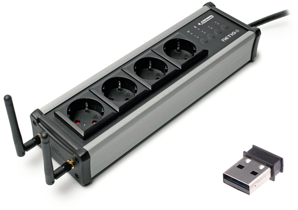
The LoligoBT is a 4-fold power strip that is powered from a wall outlet and communicates with a Windows computer via Bluetooth 4.0. LoligoBT is used for wireless software control of equipment connected to one of the four independent electrical sockets, i.e., relays turning pumps, valves, stirrers etc. ON or OFF from a distance.
Important
- DO NOT reset the LoligoBT device to factory defaults (see How to reset the LoligoBT/Netio device)!
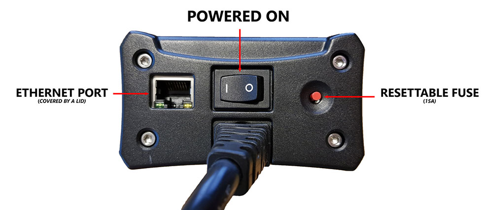
- The LoligoBT is equipped with an ethernet port. The port is covered by a lid. You should NOT remove this lid or connect an ethernet cable to the LoligoBT. It will reset the device and void the warranty!
Setup:
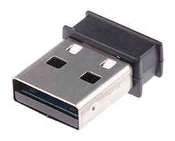
- Insert the small black USB dongle directly into your PC. Let the dongle configure itself in Windows.
- Connect the LoligoBT into a wall socket.
- Set the power switch to “l” to turn the LoligoBT on (see below):
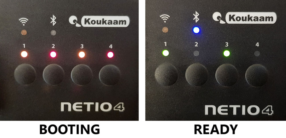
- Wait until the device is ready (see below). It takes about 50 seconds:
- COM port number: In Windows 10, go to Settings > Devices > Look for the BLUEGIGA BLUETOOTH LOW ENERGY (COM#) > Make a note of this COM port number.
- If Windows asks for a pairing code, use “123456”.
- If Windows asks for a pairing code, use “123456”.
- Open AutoResp™ as administrator (right-click).
- Select the right COM port number for this LoligoBT device.
- Your LoligoBT device is now ready to be used in AutoResp™.
How do I set up Witrox 1/Witrox 4 in AutoResp 2.3.0?
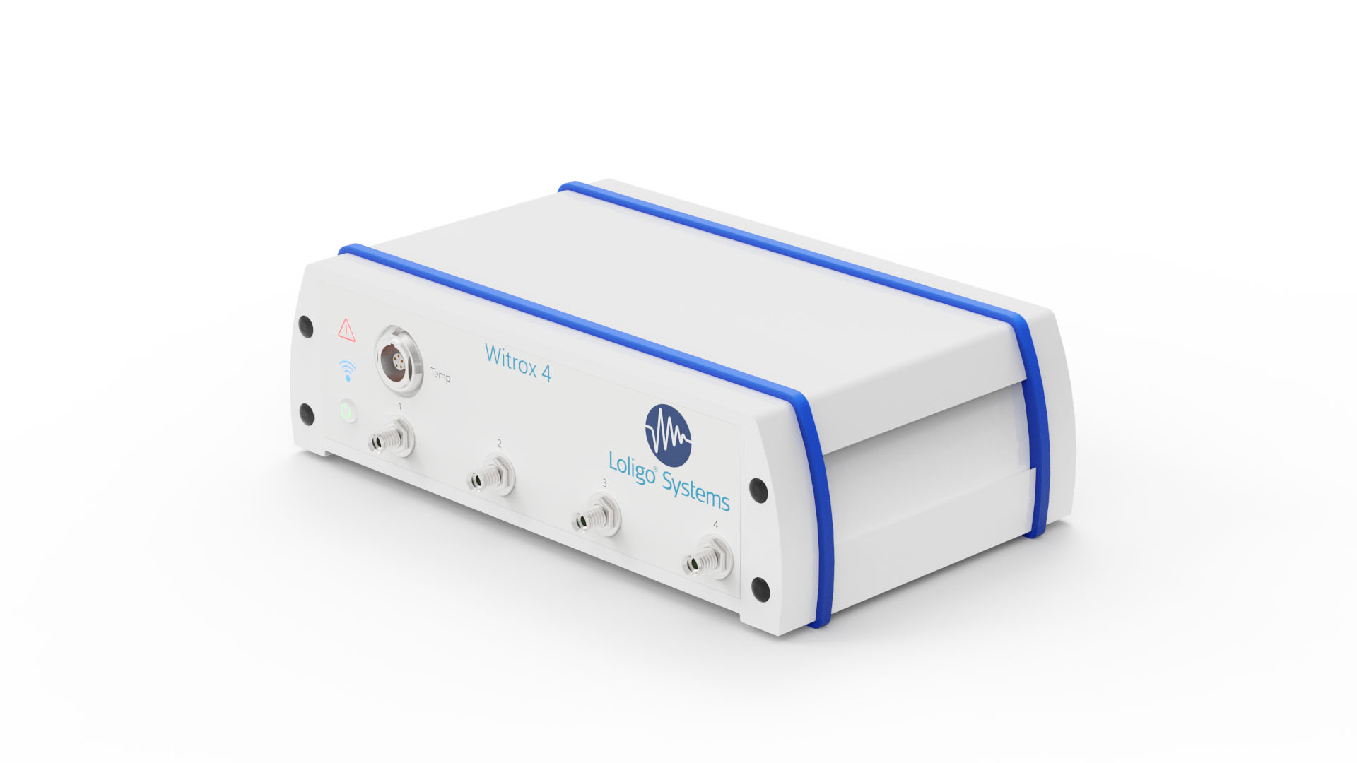
The Witrox instruments are used for measuring dissolved oxygen using fiber optic mini sensors (optodes) and for measuring temperature.
Important
- Do not use the free WitroxView software while running AutoResp™ on the same PC!
Setup
- To power the Witrox instrument, connect the DC adapter to a wall outlet and the USB power cable to the threaded socket on the backside of the instrument.
- Tip: You can power a Witrox instrument directly from your PC using a USB cable.
- Tip: You can power a Witrox instrument directly from your PC using a USB cable.
- Press the power button. The power LED will turn green. The link LED (wireless icon) will flash blue indicating that pairing mode is enabled.
- Pairing in Windows 10: Go to Settings > Devices > Add Bluetooth or other device > Choose Bluetooth > Look for Witrox and choose “Pair”.
- If Windows asks for a pairing code, use “0” (zero).
- If Windows asks for a pairing code, use “0” (zero).
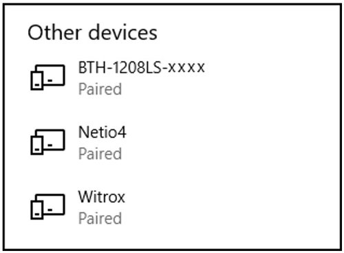
- Verify that the Witrox is paired with your PC (under Devices in Other devices list).
- COM port number: In Windows 10, go to Control Panel > Devices and Printers > Find the paired Witrox device > Right-click on the device icon > Choose Properties > Choose the Hardware tab > Look for the COM port under Standard Serial Connection via Bluetooth (COM#) > Make a note of this COM port number.
- Open AutoResp™ as administrator (right-click).
- Select the right COM port for this Witrox instrument.
- Your Witrox instrument is now ready to be used in AutoResp™.
How do I set up DAQ-BT in AutoResp 2.3.0?
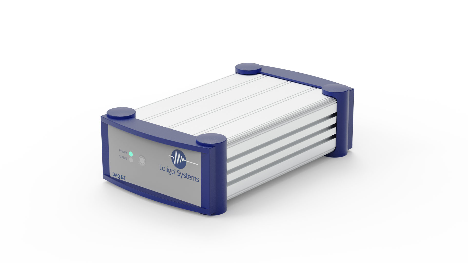
The DAQ-BT device is used for wireless data acquisition from and control of Loligo® swim tunnels. The built-in Bluetooth communication allows you to place the PC at a distance from the swim tunnel. The device has inputs and outputs for controlling and acquiring RPM data from the swim tunnel motor controller (VFC).
Setup
- To power the DAQ-BT device, connect the DC adapter to a wall outlet and the USB power cable to the threaded socket on the backside of the instrument.
- Tip: You can power a DAQ-BT instrument directly from your PC using a USB cable.
- Tip: You can power a DAQ-BT instrument directly from your PC using a USB cable.
- Press and hold the power button until the POWER and STATUS LED flash green. Pairing mode is now enabled.
- Pairing in Windows 10: Go to Settings > Devices > Add Bluetooth or other device > Choose Bluetooth > Look for BTH-1208LS-XXXX and choose “Pair”.
- If Windows asks for a pairing code, use “0000” (four zeros).
- If Windows asks for a pairing code, use “0000” (four zeros).
- Verify that the DAQ-BT is paired with your PC (under Devices in Other devices list):
- Open the program InstaCal (from Measurement Computing) as administrator (right-click).
- InstaCal will now detect and configure the DAQ-BT instrument (see below). Click OK to the following message:

- Click OK to the following message:

- The assigned board number must correspond to the board number used in AutoResp™:
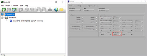
- Click File > Exit
- If the following error message appears, you must exit InstaCal and open it again as administrator:

- Open AutoResp™ as administrator (right-click).
- Select the right board number for this DAQ-BT device.
- Your DAQ-BT device is now ready to be used in AutoResp™.
WARNING: DO NOT reset the device to factory defaults!
Resetting the device to factory defaults will void the warranty and remove the pre-installed Loligo® firmware leaving the device unable to communicate with any Loligo® software.
Ways to reset the device (DON’T!!!)
The LoligoBT/NETIO4All device can be reset to factory defaults in two ways:
- By pressing and holding outlet buttons 1 and 2 when starting the device via power switch. Hold the buttons until the device beeps 3 times. During the resetting process, all the outlet LED are blinking red. As soon as reset is completed, the device beeps 3 times. Whole procedure takes about 2 minutes.
- By removing the protective cap from the ethernet port and connecting the device to a computer with an ethernet cable and resetting the device in your browser.
Contact our technical support if you experience connectivity or performance issue with the LoligoBT/NETIO4ALL.
LinkHow to place horizontal mini chambers in holder
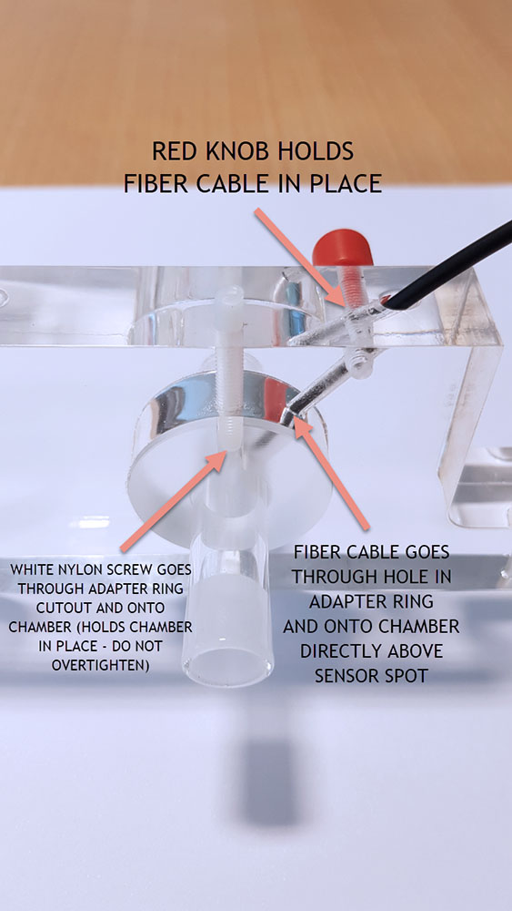
The horizontal mini chambers can be fixed in place in an acrylic holder for easier measurements.
- Place the acrylic adapter ring in the acrylic holder.
- Place the mini chamber (with mounted sensor spot on the inside) inside the adapter ring.
- Rotate the mini chamber so that the sensor spot is located directly below the hole in the adapter ring.
- While keeping the mini chamber in place, tighten the white nylon screw so that it goes through the adapter ring cutout and onto the glass chamber. Tighten until the mini chamber does not rotate/slide. DO NOT OVERTIGHTEN as it will break the mini chamber.
- Push the fiber cable through the angled hole in the holder and place cable tip onto mini chamber, so that it is directly above the sensor spot.
- Tighten red knob to hold fiber cable in place. DO NOT OVERTIGHTEN as it will break the fiber cable.
Optimizing your PC for data recording
This guide will help optimizing your PC for data recording. Note that the optimal settings may vary depending on your PC specifications, and that this guide is based on a modern Windows 10 PC.
Dedicate your PC to data recording
Recording data (e.g., video recording) can be a heavy task for many PCs. Therefore, you should make sure that your computer is focusing most of its processing power on this task. Here are some tips on how to do that:
- Close all unnecessary software. Ideally, you should only be running your data recording software (and essential Windows processes), so do not listen to music on YouTube or chat in Microsoft Teams while recording data.
- Prevent process startup. Many processes will start up automatically in the background when you power on your PC. But you can prevent unnecessary processes from doing just that:
- Open the Task manager.
- Open Startup.
- Right-click on the software (that you do not want to start up automatically)
- Choose Disable from the pop-up menu.
- Restart your PC.
- Open the Task manager.
- Go offline. Going offline will prevent many applications from running (also accidentally) during a recording:
- A quick way to go offline is to enable Airplane mode.
- Click on the internet icon in the tool bar.
- Enable Airplane mode.
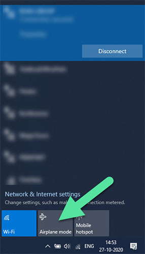
- A quick way to go offline is to enable Airplane mode.
- Pause Windows updates. You can pause Windows updates to avoid disruptions during recording. Here is how:
- Click on the Windows icon
 .
. - Open the Settings menu
 .
. - Go to Update & Security.
- Go to Windows Update.
- Choose the option Pause updates for 7 days.
- If you want to resume the updates before the 7 days have passed, click the Resume updates button near the top.
- Click on the Windows icon
- Turn off antivirus. Turning off your antivirus software can free up processing power. Remember to turn it back on again after recording.
- Choose correct USB port. If you are using USB devices (like one of our uEye cameras), you must connect the camera to an optimal USB port on the computer: USB 3 devices should be connected to a USB 3 port.
- Enable "Performance mode". Many laptops uses "best battery mode" when running on their battery only which results in reduced performance. Enable "best performance mode" instead and make sure the laptop is plugged in.
- Fingers off your PC! Once your data recording has started, you should not operate your PC – even moving the mouse curser can lower your PC’s performance!
How to clean a glass microplate
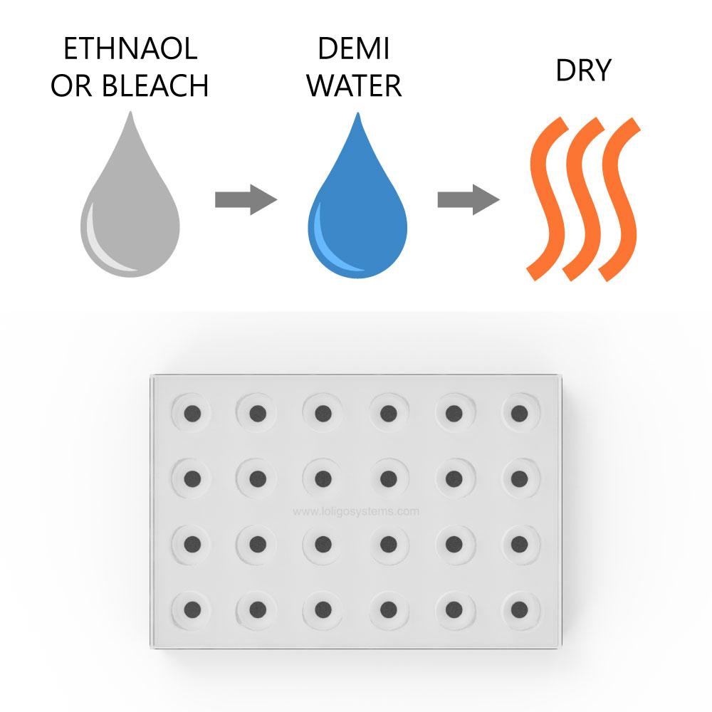
To clean the glass microplate, use ethanol (<70 % v/v), bleach (<3% H₂O₂), or mild detergent, and rinse with demi water. Then dry. If using ethanol to sterilize the spots/wells, then dry the plate thoroughly, at least 2 days at 50-60 °C in an oven, to ensure that all residues have left the sensor dye matrix.
It is recommended to perform a manual calibration after cleaning/sterilizing.
Step-by-Step Instructions using bleach
- Fill each well with 2-2.5% bleach, and ensure that there are no air bubbles in the wells.
- Leave for 10-20 Minutes.
- Empty the wells, and rinse each well thoroughly with demi water.
- Let the wells dry overnight in the dark.
- Perform a manual calibration before starting a new experiment.
Link
How to work with ground glass joints
A special technique is required when working with ground glass joints. The stopper must be inserted/removed with a twist rather than a straight pull/push.
Also, when using equipment with ground glass joints, each standard taper ground glass joint should be lightly greased with stopcock grease to ensure that the joints do not "freeze" together.
Even if ground glass joints seal well without the use of lubricants, it is advisable to lubricate them to prevent sticking and breakage. Applying non-toxic silicone (stopcock) grease will help prevent that the two parts “freeze” together.
The grease should be used only sparingly by applying thin streaks to the top (wider) half of the male joint and then seat the joint by rotating gently.
Do not apply too much grease and make sure that the grease does not spread into the chamber beyond the area of the joint, otherwise the grease can dissolved in the water and contaminate your sample.
How to grease ground glass joints:
Where to buy stopcock grease:
Link